The blog is in continuation to Processor Funamentals. Programming in Assembly language helps developers understand everything that happens under the hood. This article is everything you need to get started with assembly language and builds on to explain in detail, the load and store instructions.
Data types in Assembly Language
Right off the bat, learning any new programming language starts with the different data types. Assembly language, being a low-level programming language, deals with three main data types,
- Byte: 8 bits
- Halfword: 16 bits
- Word: 32 bits
These grant us access to every finicky detail of low-level data and memory handling.
ARM Thumb and Thumb-2 Instruction sets
Instructions are cogs used to instruct a Central Processing Unit(CPU). A group of these cogs is called the instruction set of a CPU. If you want to understand how they work internally, bump into the blog attached below. ARM instructions are 32 bits wide and operate on 32-bit data. Thumb instructions are a subset of ARM instructions and are 16-bit wide, yet they work on 32-bit data.
ARM instructions are representations of binary codes. For instance, the instructions, ADD internally could represent a 4-bit code like 1001. Analogous to this, ARM instructions are 32 bits wide and operate on 32-bit data.
For example,
- ADD R0, R0, R2 - ARM Instruction Set: Add R0 and R2, and store the result in R0.
- ADD R0, R2 - Thumb Instruction Set: Register R0 acts as the source and destination.
Bear in mind that both the instructions operate on 32-bit registers, however, "ADD" is 32 and 16 bits in ARM and Thumb IS, respectively. The Thumb instruction trades better code density for performance. Thumb-2 is a further subset that entails both 16-bit and 32-bit instruction and strikes the right balance between both code density and performance. Processor cores like Cortex-M3 and Cortex-M4 can execute only Thumb-2 Instructions.
Load-Store Instructions
RISC architectures are LOAD STORE architectures because the operations can be performed only on the registers and not explicitly on the memory.
- Load(LDR Instruction): Write a value from the memory to a register.
- Store(STR Instruction): Write a value from a register to the memory.
Syntaxes:
ldr{size}{condition} <Rd>, <AddressingMode>
str{size}{condition} <Rd>, <AddressingMode>
{size} and {condition} are optional and add to the versatility of the instructions. Rd is the destination and source register, respectively. Addressing modes can take various forms to form different nuances of the instruction.
The simplest form of LDR and STR instructions could be,
ldr    r0, =1     ;Load register with value 1
str    r0,[r1]    ;Store register r0s value in the memory address stored in the register, r1
All registers can be used for load and store instructions. Altering the R15 register (Program counter) causes the program flow to change.
Load and Store - Sizes
ldr and str, used without the "size parameter" simply transfer a word.
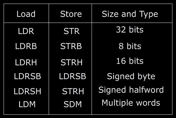
For half-word loads, the data gets placed in the Least Significant Half-word of a register; the upper half-word bits get asserted with 0s.
Consider the memory and register R0 as
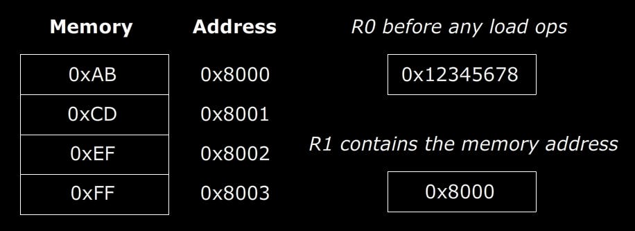
R0, post LDR operation
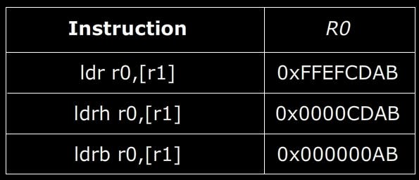
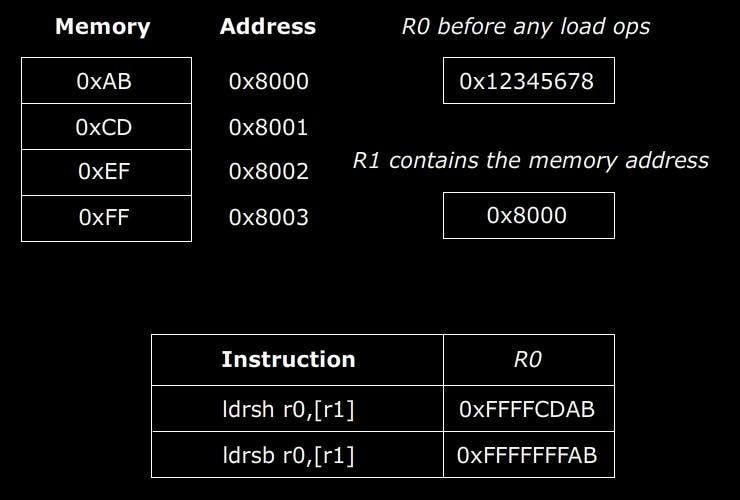
LDRSH and LDRSB are used to transfer signed data(2s complement form). These instructions, when plied, the loaded byte/half-word is passed into the sign-extend block where the data is sign-extended.
Load and Store - Addressing
The addresses for the LDR and STR instructions appear within square brackets. The tedious process of updating the addresses after load and store operations can be mitigated by using the various addressing modes.
- Offset addressing mode
An offset is applied to the address pointed by the register. For instance, if address 0x20000000 is stored in register R0, [R0,#4] will refer to 0x20000004.
;this program demonstrates offset addressing mode
        area    prgm, code, readonly
        entry
        export    __main

__main
        ldr     r0, =0x20000000       ;load register with address 0x20000000
        mov     r1, #1                ;store value 0x01 in register r1
        str     r1,[r0,#4]            ;store r1s value(0x01) in memory location 0x20000000+4 = 0x200000004

stop    b       stop
        align
        end

- Pre-indexed addressing mode
This mode updates the address register with the increment/decrement before the load/store. The syntax includes an exclamation mark following the square bracket. Assuming the register R0 has 0x2000000 and a load/store operation performed in this mode([R0,#4]!) will pre-update the register R0 with 0x20000004.
;this program demonstrates pre-index addressing mode
        area    prgm, code, readonly
        entry
        export    __main

__main
        ldr     r0, =0x20000000       ;load register with address 0x20000000
        mov     r1, #1                ;store value 0x01 in register r1
        str     r1,[r0,#4]!           ;store r1s value(0x01) in memory location 0x20000000+4 = 0x200000004
                                      ;r0 = r0+4

stop     b       stop
        align
        end

- Post-indexed addressing mode
The address is loaded from/stored into the address contained in the base register, followed by its update. The address register(R0) having 0x20000000 will be used for the load/store operation and will be post-updated().
;this program demonstrates post-index addressing mode
        area    prgm, code, readonly
        entry
        export    __main

__main
        ldr     r0, =0x20000000       ;load register with address 0x20000000
        mov     r1, #1                ;store value 0x01 in register r1
        str     r1,[r0],#4            ;store R1s value(0x01) in memory location 0x20000000
                                      ;r0 = r0+4

stop     b         stop
        align
        end

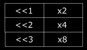
Another nuance that can save us big time is using bit shift-based multiplication.
;this program demonstrates post-index addressing mode
        area    prgm, code, readonly
        entry
        export    __main

__main
        ldr     r0, =0x20000000       ;load register with address 0x20000000
        mov     r1, #1                ;store value 0x01 in register r1
        mov     r2, #2
        str     r1,[r0,r2,lsl #1]     ;store R1s value(0x01) in memory location, 0x2000000+(2*2)

stop     b         stop
        align
        end

Endianess
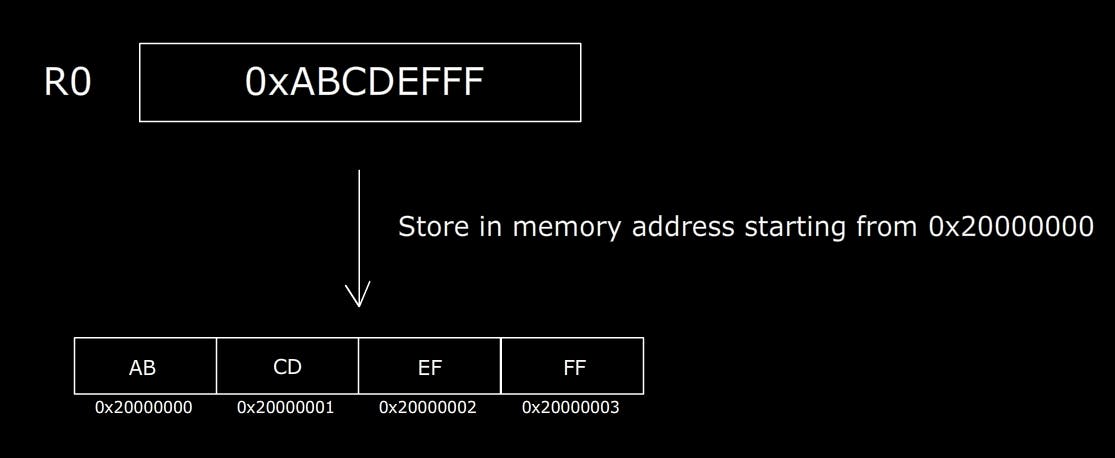
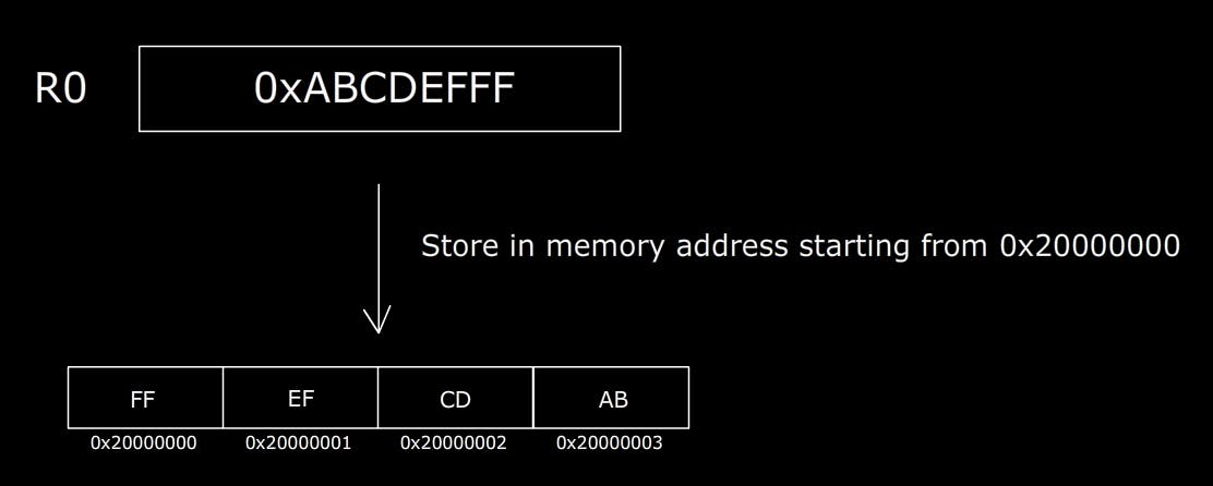
Endianness is how data bytes are stored in the computer memory. It can be of two types,
- Big Endian as in Big-End stores the byte with the highest place value first.
- Little Endian as in Little-End stores the byte with the lowest place value first. This is the default memory format for ARM processors.
With everything we've learned, let's try writing a program to swap register content.
EOR is used to perform the Logical Exclusive OR operation on registers.
;this program swaps register content

        area    swapReg, code, readonly
        entry
        export    __main

__main
        ldr        r0, =0xABCAABCA
        ldr         r1, =0xDEFDDEFD

        eor        r0,r0,r1            ;r0 = r0^r1
        eor        r1,r0,r1            ;r1 = r0^r1
        eor        r0,r0,r1            ;r0 = r0^r1

stop    b         stop
        align
        end


